Top Notch Tips About What Size Are Hidden Lines In Mm Draw Vertical Line Ggplot
These lines are used to.
What size are hidden lines in mm. Use a section view to make hidden lines visible, or use a hole callout if possible. You should not dimension to hidden lines: Hidden and visible lines are two types of lines that are used to represent the edges of an object in a technical drawing.
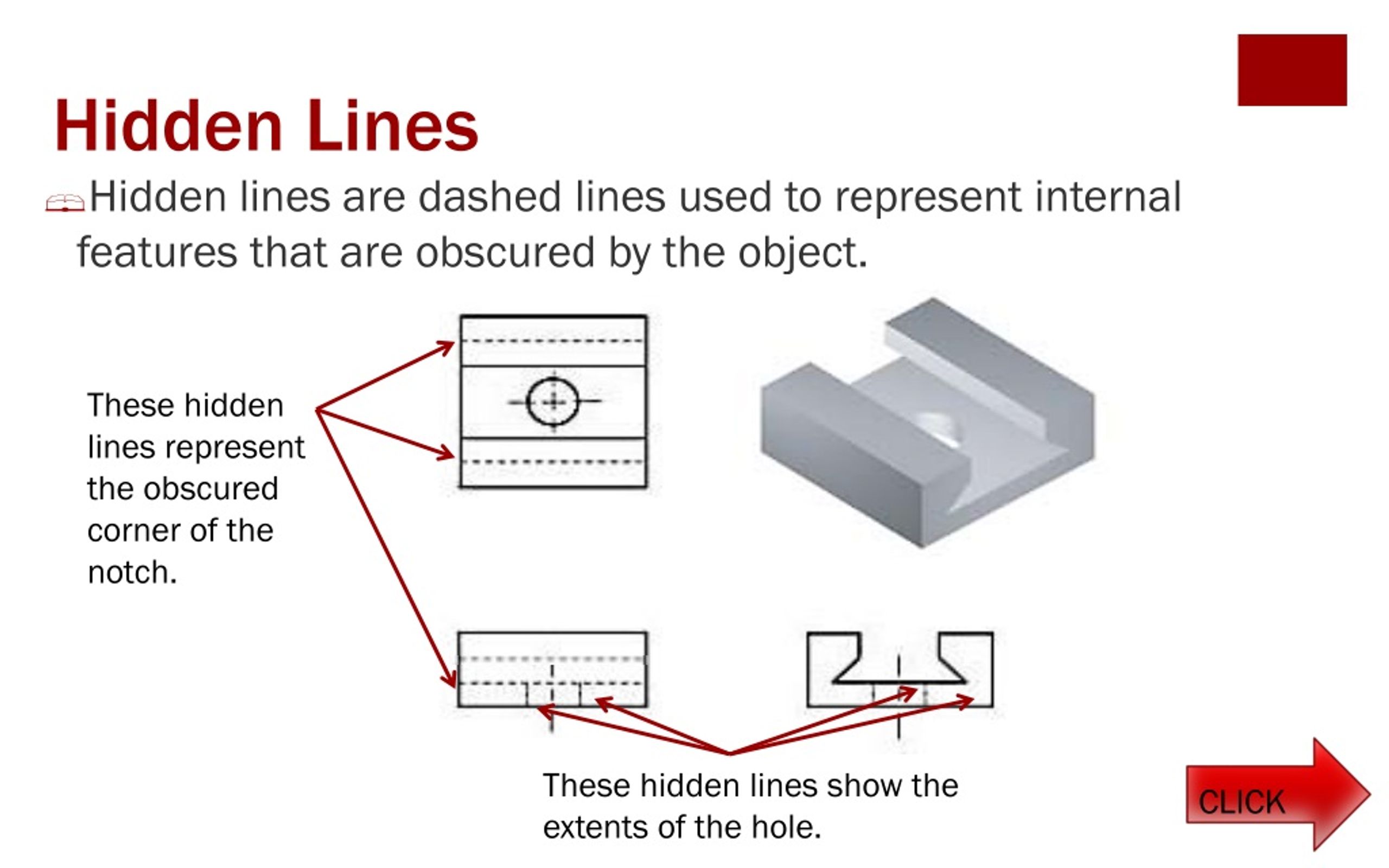
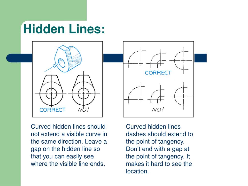
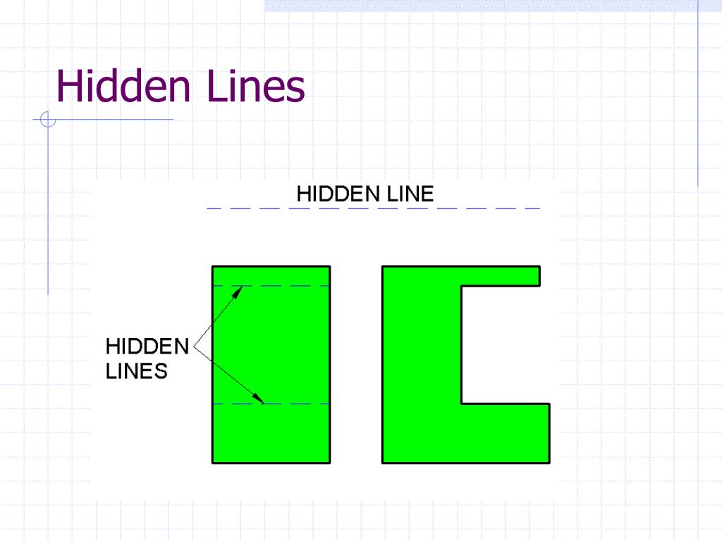
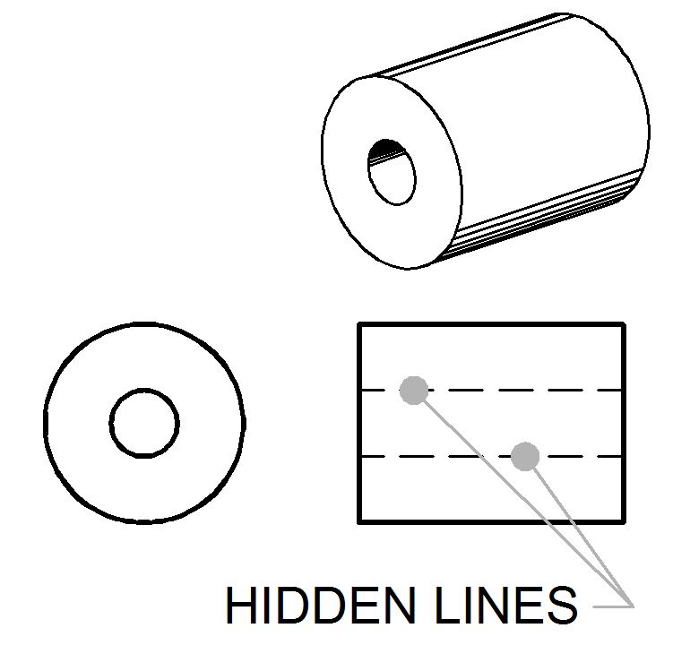
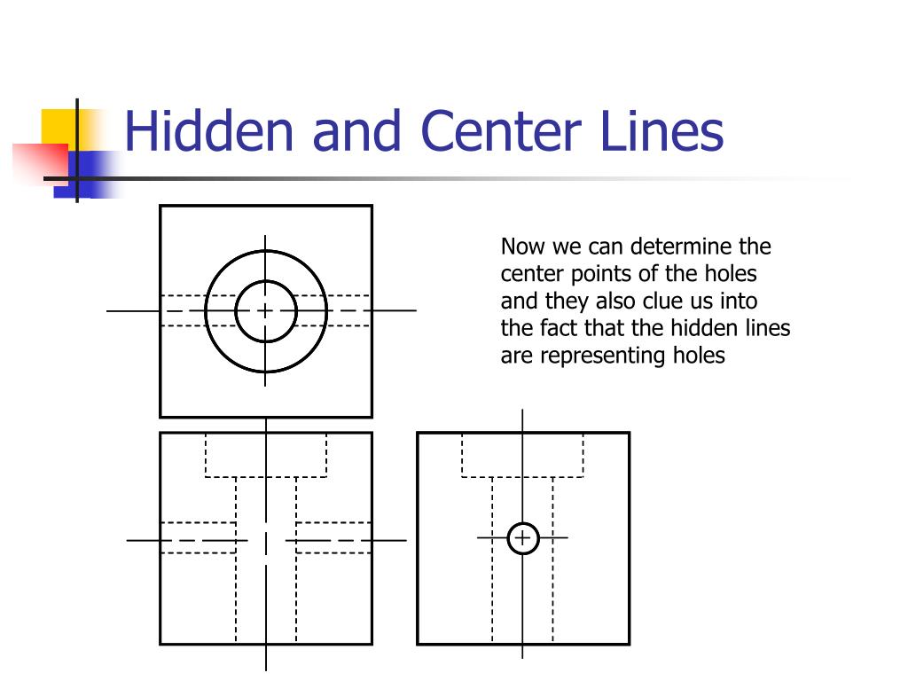
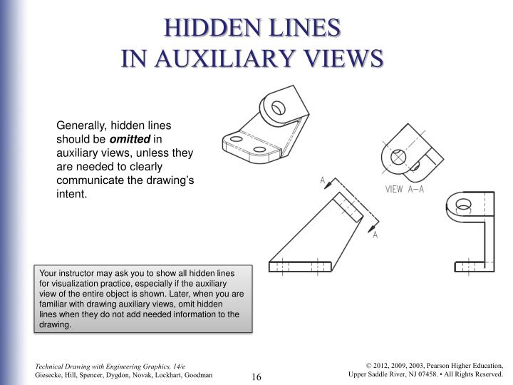
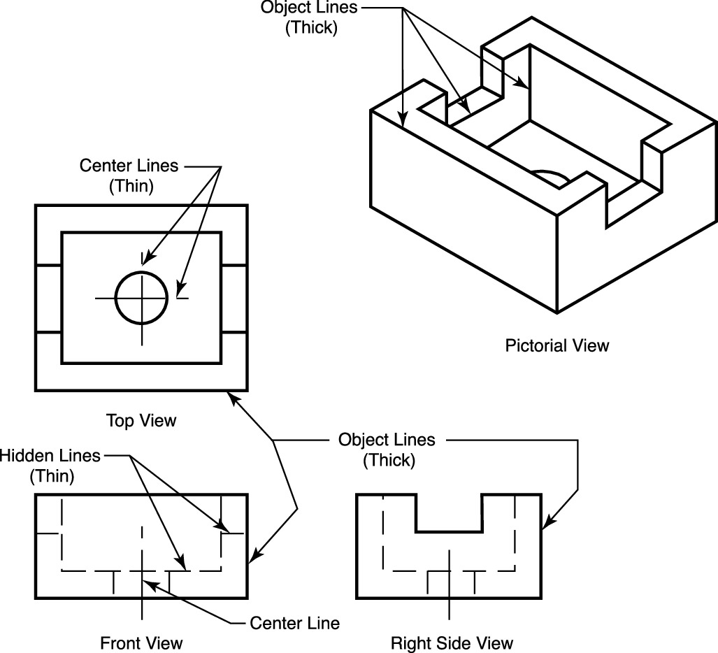
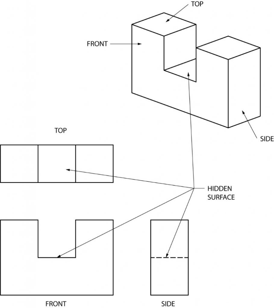
Hidden lines are used to represent features or edges that are not visible from a particular viewpoint. They are drawn as short dashes that are equally spaced. Hidden lines are dashed lines with 0.125 dashes and 0.0625 spaces to represent the cutaway from the object.
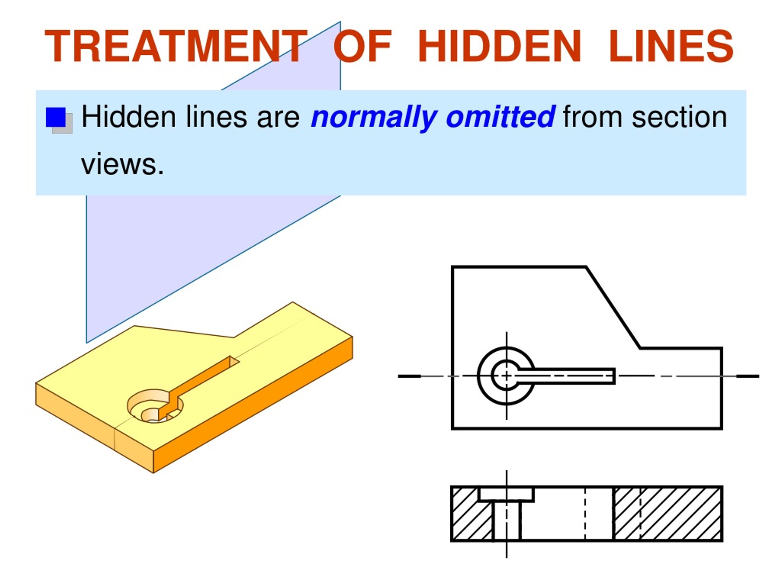
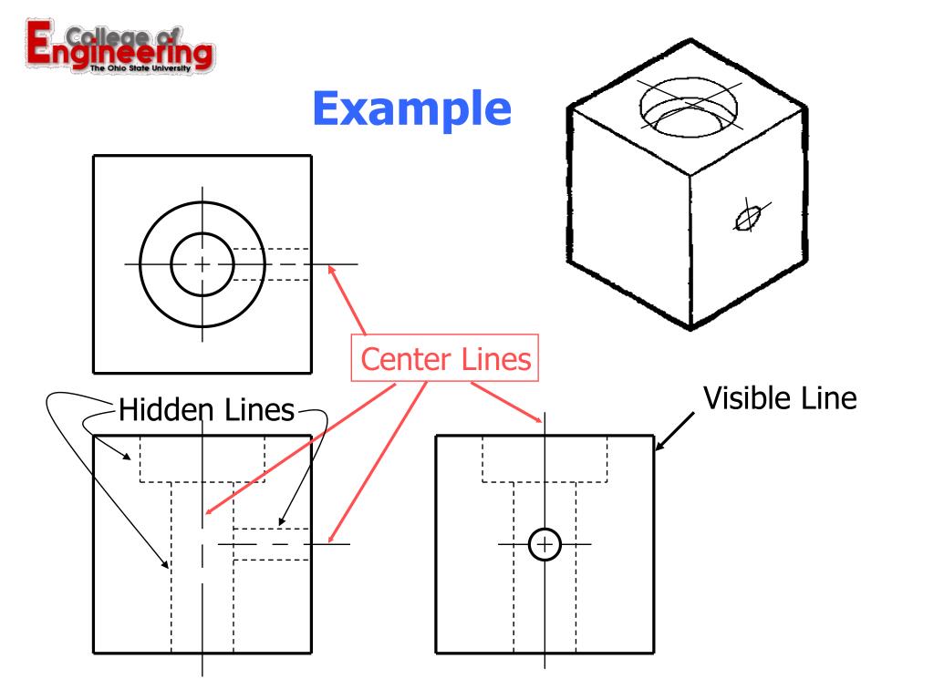
The exposed cut surface is then. In accordance with asme y14.2 standards, visible lines should be drawn with a sharp, consistent thickness (generally.6 mm) and be free of any breaks or irregularities. Hidden lines show edges and contours of important features that are obscured by the geometry of the part.
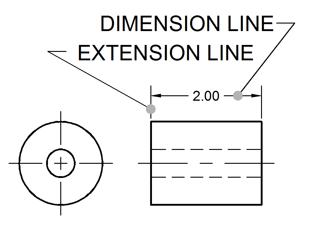
They are typically represented using short dashes or dotted lines. Dimension lines can extend 1/8″ (3 mm) past extension lines or end at extension lines. They are called hidden lines and their linetype is.
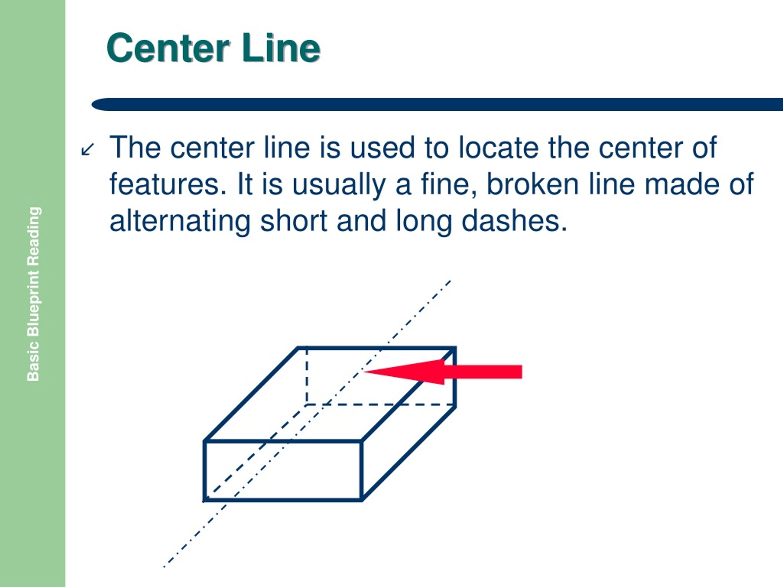
In this article, you will learn how to use hidden and visible lines to show dimensions and tolerances in your drawings, and what rules and standards you should follow. You will most likely use the 2 line display representation instead, which displays objects in the same way as the plan display representation, without hidden lines. Center lines represent axes of symmetry.
Hidden lines represent hidden edges and boundaries. Hidden lines are represented using dashed lines. Visible lines are solid and continuous, and they show the edges that.
Center lines are used to indicate the center of symmetrical objects or the center axis of cylindrical or circular shapes. You draw hidden lines 0.4 mm thick. These lines (commonly 0.18mm to 0.35mm) indicate features that are not visible in the current view but exist in the design.
For horizontal dimensions, the slash goes from bottom left to upper right. To completely describe a model in a multiview drawing, you must also show all lines or features that are hidden in that view. A sectional view represents the part of an object remaining after a portion is assumed to have been cut and removed.
Draw centerlines locating the center of a hole only if they are needed to indicate symmetry or. You will learn more about hidden lines in chapter 6. Size dimensions indicate the size of basic shapes like.
